Burks part # 20522-8 Repair Kit
Burks # 20522-8
Burks catalog # 20522-8, Kit Repair CS8M
Product Information :
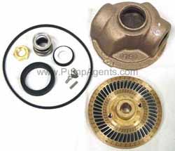
The Burks 20522-8 is a repair kit for all CS8M series pumps with standard Buna-N seal, comes with the impeller, raceway, Buna-N shaft seal, o-ring gasket, suction sleeve, raceway screws, impeller locknut, shaft key and instructions.
In many cases you may not yet need to overhaul the pump with a new impeller and raceway - it might just need to be adjusted. An Adjustable Spanner Wrench - Burks Part No. 7492 - is available for this adjustment process. Burks Turbine Pumps are unique in design and different from all other regenerative turbine pumps. An integral part of their unique design is the Life-Lok feature that provides a way to externally adjust the clearance between the impeller and raceway. This adjustment is used for precise setting of pump performance during production testing. This Life-Lok makes the Burks Turbine Pump field adjustable and allows pump performance to be restored to Inchlike new Inch after years of service, greatly extending pump life. The adjusting screw is located in the bearing frame on Base-Mounted Pumps and in the shaft extension end of the motor on Close-Coupled Pumps. A positive pre-load spring pressure is applied to the pump shaft bearing and, in turn, is transmitted to the adjusting screw. This controlled pressure eliminates bearing end play and provides a means for external adjustment of the clearance between the impeller and raceway.
To adjust the impeller first Disconnect the electrical power. Adjustment should never be attempted while pump is running. Serious damage could occur. Then Loosen the slide lock and remove the tab from the hole in adjusting screw. Next, turn the Adjusting Screw with a Spanner Wrench. At the same time, rotate the shaft back and forth with a common nail or other object placed through the hole provided for that purpose on close-coupled pumps. The shaft on base mounted pumps may be rotated by turning at the couplingend. Rotate Adjusting Screw in a clockwise direction a drag will be felt as the impeller comes into contact with the raceway. At this point, make a mark on the pump frame and adjusting screw, across one of the spanner wrenchholes Rotate the Adjusting Screw in the opposite direction to back the impeller off and provide clearancebetween it and the raceway. The proper clearance may be obtained by moving the adjusting screw approximately one half the distance between two of the spanner wrench holes as indicated by the reference marks you made earlier. Lock the Adjusting Screw in place. Insert the tab of the Slide Lock in the nearest spanner wrench hole and tighten thelock screw. Re-connect electrical power and start pump. If pump seems to labor unduly when coming up to pressure, a slight additional adjustment to increase the clearance between the impeller and raceway will be necessary. Do not allow pump to operate with insufficient clearance between those two parts. If adjustment does not restore desired performance, replacement of the impeller and raceway may be necessary. These are matching parts and must be replaced as a set.